-
Key: SYSML2-59
-
Status: closed
-
Source: DEKonsult ( Mr. Hans Peter de Koning)
-
Summary:
The graphical notation is specified in the graphical BNF in subclause 8.2.3 and the view model libraries in subclause 9.2.18 and 9.2.19. Its use is illustrated in the representative notation tables in the overview sections of Clause 7.
The overarching need is for the specification of the graphical notation to result in a clear and unambiguous human interpretable representation that is consistent within and across views, and that is consistent with the abstract syntax and the textual notation. A further goal is to achieve, as much as possible, compatibility with or smooth transition from SysML v1 notation.
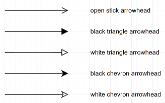
To facilitate discussion a legend of different arrowheads is given below.

The following issues with the graphical notation relate to successions, messages, flows, and succession flows as they appear in the action flow view, sequence view, and interconnection view.
- Symbols for succession edge:
- subclause 7.11.1 Table 9, example "Part with Graphical Compartment with perform actions and flows between them ..." the succession edge uses solid line and open stick arrowhead
- subclause 7.16.1, Table 14, in all examples the succession edges between actions use solid line and open stick arrowhead
- subclause 8.2.3.9 Occurrences Graphical Notation, production sq-succession uses dashed line and open stick arrowhead
- subclause 8.2.3.16 Actions Graphical Notation, production succession uses solid line and open stick arrowhead
- Symbols for message transfer edge:
- subclause 7.13.1, Table 11, in example "Message" (first) the message edge symbol between two ports of parts uses solid line and black triangle arrowhead.
- subclause 7.13.1, Table 11, in example "Message" (second) the message edge symbol between the life lines uses solid line and open stick arrowhead.
- subclause 8.2.3.9 Occurrences Graphical Notation, production sq-message uses solid line and open stick arrowhead
- Symbols for flow edge:
- subclause 7.13.1, Table 11, in example "Flow" the flow edge symbol between two parameters of actions uses solid line and black chevron arrowhead.
- subclause 7.13.1, Table 11, in example "Flow as Node" the flow edge symbol between two parameters of actions uses solid line and open stick arrowhead.
- subclause 7.14.1, Table 12, in example "Interface as Node (with flow)" the flow on interface edge between two ports uses solid line and black triangle arrowhead
- subclause 7.16.1, Table 14, in example "Action with Graphical Compartment showing standard action flow view" the flow edge between two action parameters uses solid line and black chevron arrowhead
- subclause 8.2.3.13 Connections Graphical Notation, productions flow-node-r and flow-node-l edge symbols use solid line and black triangle arrowhead
- Symbols for succession flow edge:
- Graphical BNF production and representative examples are missing
- In addition there are the following inconsistencies:
- In subclause 7.13.1, Table 11 "Connections", the labels for the entries for Flow and Message are specified inconsistently.
- In subclause 7.16.1, Table 14 "Actions", the entry for Perform Actions Swimlanes includes the notation for successions in an action flow view that is not readily distinguishable from the message notation in the sequence view in Table 11 (last entry). A succession can also be shown in a sequence view. The entry for the flow in "Action with Graphical Compartment showing standard action flow view" cannot be differentiated from a succession flow as currently shown.
- Symbols for succession edge:
-
Reported: SysML 2.0a1 — Thu, 27 Apr 2023 12:44 GMT
-
Disposition: Resolved — SysML 2.0b2
-
Disposition Summary:
Correct inconsistent graphical notation for succession, message and flow edges
This resolution ensures the following:
- Differentiation of the notation for successions and messages, applying consistently in both the action flow and sequence view.
- Leverages the approach used in SysML v1 to represent succession flows (e.g., control flows) as dashed lines with arrowheads
- Differentiation of the notation for message and flow, applying consistently in both the action flow and sequence view.
- Differentiation of non-succession flows from succession flows, applying consistently in both the action flow and sequence view.
- Consistent application of the notation for non-succession flows, succession flows, and messages across connections.
- Leverages the approach used in SysML v1 to show flows as arrowheads on a connector.
- Differentiation of the notation for successions and messages, applying consistently in both the action flow and sequence view.
-
Updated: Tue, 1 Jul 2025 14:51 GMT
-
Attachments:
- 2023-12-18-Graphical-Notation-Successions-Messages-Flows.pdf 746 kB (application/pdf)
- Action with Loop-1.svg 16 kB (image/svg+xml)
- Action with Loop-2.svg 21 kB (image/svg+xml)
- Action-Flow-Accept-and-Send-1.svg 24 kB (image/svg+xml)
- Control Nodes.svg 18 kB (image/svg+xml)
- Flow-1-ends.svg 7 kB (image/svg+xml)
- Graphical Compartment-Action Flow.svg 13 kB (image/svg+xml)
- Graphical Compartment-Swimlane-1.svg 7 kB (image/svg+xml)
- Graphical Compartment-Swimlane-6.svg 22 kB (image/svg+xml)
- Graphical Compartment-Swimlane-7.svg 17 kB (image/svg+xml)
- Interface-as-Node-with-Flow.svg 19 kB (image/svg+xml)
- Interface-as-Node.svg 19 kB (image/svg+xml)
- Item-Flow-as-Node.svg 22 kB (image/svg+xml)
- Message-2-ends.svg 8 kB (image/svg+xml)
- Message-ends.svg 6 kB (image/svg+xml)
- Succession-ends-1.svg 5 kB (image/svg+xml)
- Succession-ends-2.svg 4 kB (image/svg+xml)
- legend-arrowheads.png 15 kB (image/png)
- sysml2-568-a-succession.jpg 12 kB (image/jpeg)
- sysml2-568-flow-connection-kw.jpg 11 kB (image/jpeg)
- sysml2-568-flow-connection.jpg 12 kB (image/jpeg)
- sysml2-568-flow-node-l.jpg 6 kB (image/jpeg)
- sysml2-568-flow-node-r.jpg 7 kB (image/jpeg)
- sysml2-568-interface-connection.jpg 20 kB (image/jpeg)
- sysml2-568-message-connection-1.jpg 12 kB (image/jpeg)
- sysml2-568-message-connection-kw.jpg 14 kB (image/jpeg)
- sysml2-568-message-connection.jpg 13 kB (image/jpeg)
- sysml2-568-message-node-l.jpg 8 kB (image/jpeg)
- sysml2-568-message-node-r.jpg 8 kB (image/jpeg)
- sysml2-568-sflow-node-l.jpg 8 kB (image/jpeg)
- sysml2-568-sflow-node-r.jpg 9 kB (image/jpeg)
- sysml2-568-sq-message.jpg 10 kB (image/jpeg)
- sysml2-568-sq-succession.jpg 11 kB (image/jpeg)
- sysml2-568-sq-succession1.jpg 13 kB (image/jpeg)
- sysml2-568-succession-connection.jpg 15 kB (image/jpeg)
- sysml2-568-succession-flow-connection-kw.jpg 17 kB (image/jpeg)
- sysml2-568-succession-flow-connection.jpg 15 kB (image/jpeg)
SYSML2 — Inconsistent graphical notation for succession, message and flow edges
- Key: SYSML2-59
- OMG Task Force: Systems Modeling Language (SysML) 2.0 FTF